Digital Communication Training
Hotline: +84 906 988 447
Head Office: Ho Chi Minh City
- Tel: +84 2839 778 269 / 3601 6797
- Email: [email protected]
- Add: 487 Cong Hoa Street, Tan Binh Ward, Ho Chi Minh City, Vietnam
Office: Bac Ninh City
- Tel: +84 222 730 0180
- Email: [email protected]
- Add: 184 Binh Than Street, Vo Cuong Ward, Bac Ninh, Vietnam
-
 Technical Counseling
100% Free
Technical Counseling
100% Free
-
 Free Shipping
For 3.000.000vnd Order
Free Shipping
For 3.000.000vnd Order
Specification
Data is being updated
Description
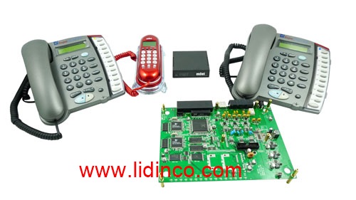
Digital Communication Training
1. Training Objectives:
- Understand basic digital communication theory
- Design and practice digital modem
- Understand the applications of balanced modulation circuits
- Understand the application of digital modem
2. Practical exercises:
- Line decoding (unipolar, bipolar, etc.)
- Line decoding (monopole, bipolar, AMI, Manchester, etc.)
- Pulse Width Modulation / Pulse Width Demodulation
- PCM modulation / Delta Demodulation
- ASK modulation/ ASK Demodulation
- FSM modulation / FSK Demodulation
- PSK modulation / PSK Demodulation
- QPSK modulation / QPSK Demodulation
3. Detailed overview of the exercises:
Bài 1 | Line Code Encoder and Decoder Experiments Module |
| Lab 1 | Line Code Encoder |
| Experiment 1 | Unipolar and Bipolar NRZ Signal Encoder (Signal: TTL, Data Rate: 1 kbps ~ 4 kbps) |
| Experiment 2 | Unipolar and Bipolar RZ Signal Encoder (Signal: TTL, Data Rate: 1 kbps ~ 2.5 kbps, CLK: 2 kHz ~ 5 kHz) |
| Experiment 3 | AMI Signal Encoder (Signal: TTL, Data Rate: 50 bps ~ 250 bps, CLK: 100 Hz ~ 500 Hz) |
| Experiment 4 | Manchester Signal Encoder (Signal: TTL, Data Rate: 100 bps ~ 400 bps, CLK: 200 Hz ~ 800 Hz) |
| Lab 2 | Line Code Decoder |
| Experiment 1 | Unipolar and Bipolar NRZ Signal Decoder (Signal: TTL, Data Rate: 1 kbps ~ 4 kbps) |
| Experiment 2 | Unipolar and Bipolar RZ Signal Decoder (Signal: TTL, Data Rate: 1 kbps ~ 2.5 kbps, CLK: 2 kHz ~ 5 kHz) |
| Experiment 3 | AMI Signal Decoder (Signal: TTL, Data Rate: 50 bps ~ 250 bps, CLK: 100 Hz ~ 500 Hz) |
| Experiment 4 | Manchester Signal Decoder (Signal: TTL, Data Rate: 100 bps ~ 400 bps, CLK: 200 Hz ~ 800 |
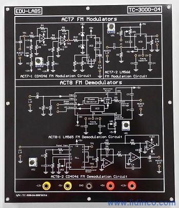
Bài 2 | PWM (Pulse Width) Modulation and Demodulation Experiments Module |
| Lab 3 | Pulse Width Modulator |
| Experiment 1 | UA741 PWM Circuit (Carrier Signal: 1.5 kHz ~ 2 kHz; Audio Signal Frequency: 500Hz) |
| Experiment 2 | LM566 PWM Circuit (Carrier Signal: 5 kHz ~ 10 kHz; Audio Signal Frequency: 1 kHz) |
| Lab 4 | Pulse Width Demodulator |
| Experiment 1 | PWM Demodulation Circuit (Carrier Signal: 5 kHz ~ 6 kHz; Audio Signal Frequency: 500 Hz ~ 700 Hz) |
Bài 3 | PCM (Pulse Code) Modulation and Demodulation Experiments Module |
| Lab 5 | PCM Modulator |
| Experiment 1 | PCM Modulator (Built-in Sample Frequency: 8 kHz, Built-in Operation Frequency: 2048 kHz, Audio Signal: 100 Hz ~ 2 kHz) |
| Experiment 2 | |
| Lab 6 | PCM Demodulator |
| Experiment 1 | PCM Demodulator (Built-in Sample Frequency: 8 kHz, Built-in Operation Frequency: 2048 kHz, Audio Signal: 100 Hz ~ 2 kHz) |
4. Practical support tools (option)
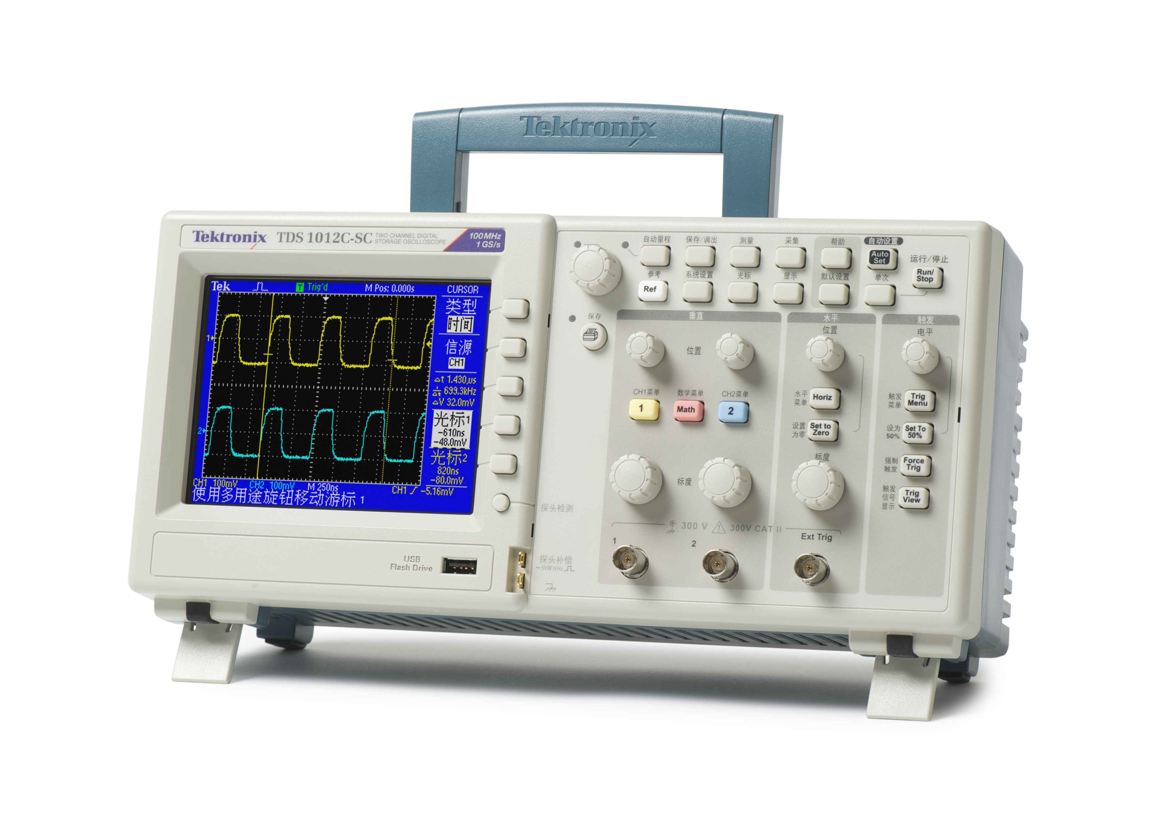
| TC-DSO-602 | 60MHz Digital Storage Oscilloscope | |
| Bandwidth with 2 Input Channels | 60 MHz |
| Real-Time | 250MSa/s | |
| Equivalent-Time Sampling | 25GSa/s | |
| Memory Length per Channel | 4k | |
| Peak Detect as Fast as | 10ns | |
| Save/Recall of Front Panel Settings & Waveforms | 15 | |
| Display | 5.6" TFT Color | |
| Auto Measurements | 19 | |
| Arithmetic Operators | Add, Subtract, FFT | |
| PC Connection | USB Port | |
| PC Interface | Real Time Software Package | |
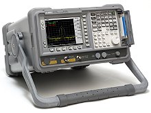
| TC-SA-505 | 500MHz Spectrum Analyzer | |
| Frequency range | 0.15~500MHz |
| Center frequency display Accuracy | ±100kHz | |
| Marker accuracy | (0.1%span+100kHz) | |
| Resolution of frequency display | 100kHz (4.5digit LED) | |
| Frequency Scanwidth Accuracy | ±10% | |
| IF bandwidth (-3dB) | 400kHz and 20kHz | |
| Video-filter (ON) | 4kHz | |
| Sweep rate | 43Hz | |
| Amplitude range | -100dBm to +13dBm | |
Accessories


Information
-
Current Range:
-
Voltage Range:
-
Display Resolution:
-
Accuracy:
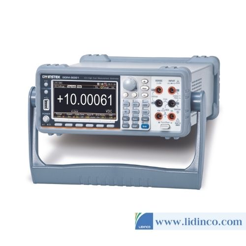
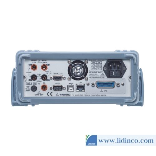
Dual Measurement Multimeter GW Instek GDM-9060
Contact


Reviews & Comments
Please login to write review!